Spare parts for GTO 52
| Code | Descr | pcs |
|---|---|---|
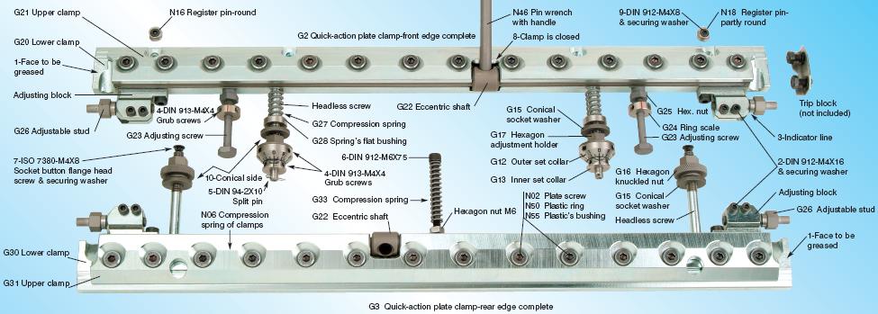
| G2 | Quick-action plate clamp-front edge complete | 1 |
| G3 | Quick-action plate clamp-rear edge complete | 1 |
| G12 | Outer set collar | 2 |
| G13 | Inner set collar | 2 |
| G15 | Conical socket washer | 4 |
| G16 | Operating hexagon knuckled nut | 2 |
| G17 | Operating hexagon adjustment holder | 2 |
| G20 | Lower front clamp (body) | 1 |
| G21 | Upper front clamp (lid) | 1 |
| G22 | Eccentric shaft | 2 |
| G23 | Adjusting screw | 2 |
| G24 | Ring scale of adjusting screw | 2 |
| G25 | Hexagon nut of adjusting screw | 2 |
| G26 | Adjustable stud | 4 |
| G27 | Compression spring | 2 |
| G28 | Springs flat bushing | 2 |
| G30 | Lower rear clamp (body) | 1 |
| G31 | Upper rear clamp (lid) | 1 |
| G33 | Compression spring | 1 |
| N02 | Hexagon socket countersunk head screw M8X20 | 28 |
| N06 | Compression spring of clamp | 13 |
| N16 | Register pin-round | 1 |
| N18 | Register pin-partly round | 1 |
| N46 | Pin wrench with handle | 1 |
| N50 | Securing plastic ring | 28 |
| N55 | Bushing of securing plastic ring | 28 |
Figures
| # | Descr | pcs |
|---|---|---|
| 1 | Face to be greased | 4 pos |
| 2 | Hexagon socket head cap screw DIN 912-M4X16 & securing washer | 8 pcs |
| 3 | Indicator line of the adjustable stud | 4 pos |
| 4 | Hexagon socket set screw DIN 913-M4X4 | 12 pcs |
| 5 | Split pin DIN 94-2X10 | 2 pcs |
| 6 | Hexagon socket head cap screw DIN 912-M6X75 with hexagon nut | 1 pc |
| 7 | Socket button flange head screw ISO 7380-M4X8 & securing washer | 2 pcs |
| 8 | Place of pin wrench when the clamp is closed | 1 pos |
| 9 | Hexagon socket head cap screw DIN 912-M4X8 & securing washer | 2 pcs |
| 10 | The conical side of the conical socket washer | 4 pos |
The placement of Plate Speed Clamps for GTO 52
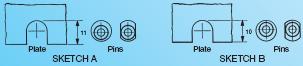
Before you place the new speed clamps onto the machine, please check that the two register pins N16 & N18 are at their correct distance and correct side. If they are placed incorrectly, they will need to be changed to the correct position or sides by loosening the small screws (fig.9) that hold them. The difference between the two sides of pins is shown below in sketches A & B. If you use plates with no holes then you remove the two register pins. If in future you use plates with holes, you reinstall them very easily and simply.
Before you start the placement of the new speed clamps, clean the grooves of the cylinder well. Place a fine coat of grease on the bottom of each clamp and on the two sides (fig.1) where the trip blocks hold the clamp in the cylinder. Start by placing the screw M6x75 (fig.6) along with its compression spring G33 into the threaded bushing and then add its nut. Place the front clamp in its position after you have first placed the springs G27 and the spring flat bushings G28 on the headless screws.
Screw the side trip blocks at their position. In order to place them easily, use a steel strip of 0,1mm thickness between the trip block and the clamp. Tighten well their screws and then remove the steel strip. Place the 2 adjusting screws G23 in their position together with the ring scale G24 and the hexagon nut G25. Continue with the placement of the indicator sets. Pay attention to the conical socket washer G15 so that is placed on the correct side. The conical side (fig.10) will be adjacent to the corresponding side of the hexagon adjustment holder G17. When you finish the placement of the indicator sets of the front clamp, place the split pins (fig.5) in their position and secure them. Place the rear clamp in its position, screw and tighten the trip blocks, in the same way as you did in the front clamp. Screw the hexagon knuckled nuts G16 provided that you have first placed the conical socket washers G15 on the right side. Place along with the security spring washers the two socket button flange head screws (fig.7) on the top of the headless screws. Screw into its place the middle screw (fig.6) to the right depth and tighten its hexagon nut. The upper and lower part of the clamps are connected together with a series of Hexagon socket countersunk head screws N02-M8X20 that are for adjusting, when required, the pressure that holds the plate. The adjustment is always regulated with the plate tightened. For the above adjustment, you must use a long hexagon socket key 5mm by moving it only a little. You have to use some strength because the above screws are secured with a plastic ring N50/N55.
There are compression springs N06 between the two parts of the clamp that help to open the upper part (of the clamp). On the side ends of the clamp, on each one of the adjusting blocks there are two hexagon socket head cap screws (fig.2) that are only to keep the adjustable studs G26 which are to be moved slightly tightened. The upper clamp opens and closes with the pin wrench with handle N46. In order to close the clamp, you have to move it forward to the lid end (fig.8). For the opening of the clamp, the pin wrench has to be moved backwards until you feel that it has fallen into a flat gap. The placement of the clamps in the center of the cylinder or the arrangement of the left and right is done with the two adjustable studs G26 on which there are indicators (fig.3) for placing the clamps in the center. The adjustment of the front clamp forwards-backwards, to the correct place, meaning in position “O” for the start of the placement of the new plate, is done with the two sets precise indicators G12 & G13. Each set of indicators has two x two hexagon socket set screws (fig.4) which with a hexagon socket screw key 2mm, regulate or adjust the position “O”. With the use of the two adjusting screws G23, the front clamp is held fixed. The correct distance between the face of the clamp and the face of the cylinders groove is about 2-3mm. Basically the operation of the new speed clamps is the same as the old ones. The difference is that these speed clamps hold the plate securely, permanently and are for a long life use.