Spare parts for HEIDELBERG ROTASPEED / SORS / SM102
| Code | Descr | pcs |
|---|---|---|
| H-102 | Whole set | 1 |
| H2 | Quick-action plate clamp-front edge complete | 1 |
| H3 | Quick-action plate clamp-rear edge complete | 1 |
| H10 | Compression spring of self-centering system | 2 |
| H11 | Springs shaft of self-centering system | 2 |
| H16 | Compression main spring | 4 |
| H18 | Double adjusting screw | 1 |
| H19 | End adjusting screw | 4 |
| H20 | Lower part-body of front clamp | 1 |
| H21A | Left part of upper front clamp (lid) | 1 |
| H21B | Right part of upper front clamp (lid) | 1 |
| H22A | Left eccentric shaft of front clamp | 1 |
| H22B | Right eccentric shaft of front clamp | 1 |
| H23 | Middle retainer part | 1 |
| H24 | Side end retainer part | 2 |
| H25 | Side operating screw of front clamp with ring scale | 2 |
| H26 | Middle operating screw of front clamp | 2 |
| H27 | Adjusting screw of front clamp | 2 |
| H30A | Lower left part-body of rear split clamp | 1 |
| H30B | Lower right part-body of rear split clamp | 1 |
| H31A | Left part of upper rear split clamp (lid) | 1 |
| H31B | Right part of upper rear split clamp (lid) | 1 |
| H32A | Left eccentric shaft of rear clamp | 1 |
| H32B | Right eccentric shaft of rear clamp | 1 |
| H35 | Operating screw of rear clamp | 4 |
| H36 | Inner steel blade of fast and parallel shift mechanism | 1 |
| H37 | Outer steel blade of fast and parallel shift mechanism | 1 |
| N01 | Hexagon socket countersunk head screw M10x35 | 44 |
| N09 | Compression spring of clamps lid | 16 |
| N12 | Compression spring of indicator set | 2 |
| N17 | Register pin-round | 1 |
| N19 | Register pin-partly round | 1 |
| N27 | Springs bushing of indicator set | 2 |
| N30 | Ring scale of front clamps operating screw H25 | 2 |
| N35 | Indicator set | 2 |
| N42 | Pin wrench Ί11Γ17mm | 1 |
| N52 | Securing plastic ring | 44 |
| N57 | Bushing of securing plastic ring | 44 |
| N61 | Toothed screw-wheel of fast and parallel shifting mechanism | 1 |
| N68 | Mechanism for placing and removing the clamps safely | 2 |
Figures
| # | Descr | pcs |
|---|---|---|
| 1 | Face to be | greased |
| 3 | Hexagon socket head cap screw DIN 912-M6X16 & securing washer | 9 pcs |
| 4 | Lines of operating screws H25 ring scale-front clamp | 2 pos |
| 5 | Line of operating screws H35 ring-rear clamp | 4 pos |
| 6 | Middle line of indicator set | 2 pos |
| 7 | Hexagon socket set screw DIN 913-MX4 (Grub screw) | 4 pcs |
| 8 | Place of pin wrench when the clamp is closed | 4 pos |
| 9 | Hexagon socket head cap screw DIN 912-M4X16 & securing washer | 2 pcs |
| 10 | Groove of middle retainer part H23 | 1 pos |
| 11 | DIN 94-5X25 Split pin | 2 pcs |
The placement of Speed Clamps for HEIDELBERG ROTASPEED / SORS / SM102
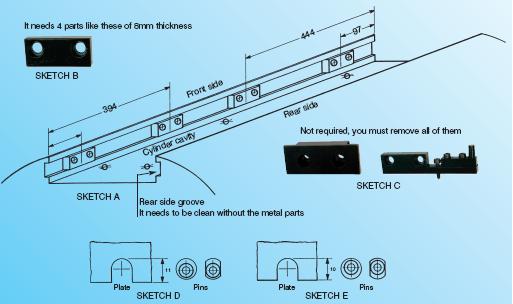
Remove the old clamps along with their retainer parts, the springs and the indicators to which they are screwed in the center of the cylinder cavity. At the rear side of the cylinder cavity, in the groove, there are 4 metal parts screwed with two hexagon socket head cap screws. Remove them as they are no longer required in this position. On the grooves front side of the cylinder cavity, there are some different metal parts as these in sketch C. Remove all these metal parts apart from these with thickness 8mm which are placed in the positions you can see in sketch A. You must complete the missing metal parts with those that have been removed from the rear groove and place them in the position shown in sketch A. Clean the whole cylinder cavity well and particularly the groove of the rear side, where you removed the steel parts.
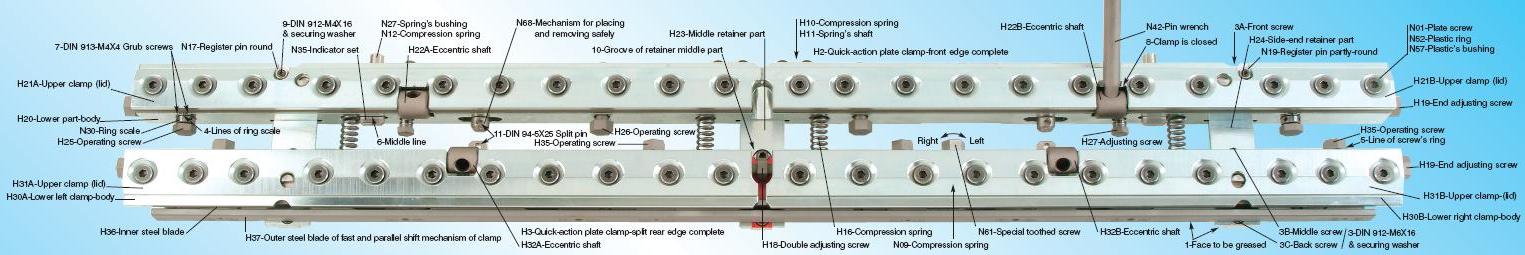
Check the front clamp if the two register pins N17 & N19 are at their correct sides depending on what kind of punch machine for the plate you use because there is a difference of 1mm in the depth of cutting the plate between the various punch machines. If the register pins need to be changed, you have to loosen the screws (fig.9) that hold them. You remove them and you reinstall them on their opposite sides. The difference between the two sides of pins is shown in sketches D and E. If you use plates with no holes then you remove the two register pins. If in future you use plates with holes, you reinstall them very easily. Spread a fine film of grease (fig.1) on the “inner” face of the retainer parts H23 & H24 of the clamps, on the face of the steel blade H37 for the fast and parallel shifting mechanism for the rear clamp and on the bottom of the cylinder cavity. Place the clamps in their positions in the cylinder cavity as they are connected by “the mechanism for placing and removing safely” N68 secured with pins (fig.11). The springs H16 are now compressed and the three retainer parts H24- H23-H24 are in their place. As they are connected, place and screw without tightening the front screws (fig.3A) of the three retainer parts of clamps if there are holes in the bottoms front side of the cylinder cavity. With the help of the two aluminum wrenches, remove the pins (fig.11) that keep the clamps connected and the springs H16 are released. Screw the middle screws (fig.3B) on the three retainer parts again without tightening them. Unscrew the 4 operating screws H35 of the rear clamp and the 4 operating screws H25/H26 of the front clamp at about 4mm. Turn the special toothed screw N61 (red) of the fast and parallel shifting mechanism to the right so as to leave space between the outer steel blade H37 and the inner steel blade H36 for the aluminum wrench in order to move the clamp backwards. Place and screw the back screws (fig.3C) of the retainer parts of clamps and tighten them completely. By turning left the special toothed screw N61 (red), you approach again the clamp towards the side of the cylinder. Restore the 4 operating screws of both clamps H35, H25/H26 and the special adjusting screw H27 into their initial positions. Tighten completely the middle screws (fig.3B) of the three retainer parts of clamps. With the help of the aluminum wrench, remove the front clamp so as to leave space in order to tighten the front screws (fig.3A) completely, if there are screws there. The new speed clamps are now in place.
The operation of Speed Clamps
The upper clamp opens and closes with the pin wrench N42. In order to close the clamp, you have to move it forward to the lid end (fig.8). For the opening of the clamp, the pin wrench has to be moved backwards until you feel that it has fallen into a flat gap. The upper and lower parts of the clamps are connected together with a series of Hexagon socket countersunk head screws N01-M10X35 that are for adjusting, when required, the pressure that holds the plate. The adjustment is always regulated with the plate tightened. For the above adjustment, you must use a long hexagon socket key 6mm by moving it only a little. You have to use some strength because the above screws are secured with a plastic ring N52/N57. There are compression springs N09 between the two parts of the clamp that help to open the upper part (lid).
In order to place the new plate you have to do the following:
FRONT CLAMP: The end adjusting screws H19 must not push the clamp right or left so that the self-centering mechanism H10/H11 can keep the clamp automatically in the center. If during the set-up you use the end adjusting screws to move the clamp right or left, keep these screws tightened till the end of the particular work. By the two operating side screws H25 place the clamp in position “O”. In this position, the horizontal line (fig.4) of the ring scale N30 is aligned with the face of the clamp and the bold vertical line is on the top. If later the indicator needs correction, there are two small screws (fig.7) that will put it in the right place. You can also place the clamp in position “O” by using the two special adjusting screws H27. These screws are not for the stretching of the plate, if you use them, they always remain in the same position where you have adjusted them. Unscrewing the 4 operating screws H25/H26, the clamp by these two screws remains in the standard position “O”. If during the set up you need to move the clamp forward, unscrew the adjusting screws H27 and after the printing process place them back to their correct positions with the help of the rings line. If they are not useful, unscrew them a few mm and they are as they do not really exist there. (These operating screws are secured with a plastic to turn hard). For the above adjustment, you can also use the two indicator sets N35 so as the middle thick line (fig.6) to be aligned with the face of the clamp.
REAR CLAMP: At first, use the special toothed screw (red) N61, which you turn left, to move the clamp toward the side of the cylinder. Place the 4 operating rear clamp screws H35 in position “O”. In this position, the horizontal middle line (fig.5) of the screws ring is aligned with the face of the clamp. Bring the two pieces of the rear clamp in the center by using either the end screws H19 or by pushing the clamp. Align the two parts of the split rear clamp with the groove (fig.10) of the middle retainer part H23 and correct the margin between them by using the double adjusting screw H18. Place the new plate as always. Remember to press the lever wrench N42 so that the clamp is closed and the lever wrench touches the upper part of the clamp (fig.8). It is better not to close the first part of the clamp to the end. It is preferable to close the second immediately and then go back to the first for the final closure. In this way the plate does not warp. After that, turn the special toothed screw (red) N61 of the mechanism, to the right, for fast shifting of the rear clamp.
ATTENTION: This special screw (red) N61 must be turned up to the end, until you feel that it has reached the end of its cycle. SPECIAL ATTENTION MUST BE TAKEN IF IT IS DIFFICULT TO BE TURNED. IT IS NECESSARY TO UNSCREW LIGHTLY THE 4 OPERATING SCREWS H35 OF THE CLAMP FOR THE STRETCHING OF THE PLATE. THIS SPECIAL SCREW IS NOT FOR COMPLETELY STRETCHING THE PLATE. IT IS JUST FOR MOVING THE CLAMP IMMEDIATELY, WITHOUT USING MUCH FORCE. The function of the special screw (red) N61 has been completed. As mentioned above do not use this special screw for the final stretching of the plate or for the different adjustments on the clamps. Tighten the 4 operating rear clamps screws H35 completely and do the same at the front clamps operating screws H25/H26. From now on, the operation of the clamps for the final coincidence of the colors or for the corrections, is, as it was with the old clamps.