Spare parts for HEIDELBERG SORM/SM72
| Code | Descr | pcs |
|---|---|---|
| SORM-SM72-1 | Whole set-rear clamp solid | 1 |
| SORM-SM72-2 | Whole set-rear clamp split | 1 |
| G12 | Outer set collar | 2 |
| G13 | Inner set collar | 2 |
| S2 | Quick-action plate clamp-front edge complete | 1 |
| S3-1 | Quick-action plate clamp-solid rear edge complete | 1 |
| S3-2 | Quick-action plate clamp-split rear edge complete | -1 |
| S20 | Lower front clamp | 1 |
| S21A | Left part of upper front clamp | 1 |
| S21B | Right part of upper front clamp | 1 |
| S22A | Left eccentric shaft of front clamp & right of rear clamp solid |
2 |
| S22B | Right eccentric shaft of front clamp & left of rear clamp solid |
2 |
| S23 | Support middle bar of front clamp | 1 |
| S24 | Side end retainer part | 4 |
| S25 | Spacer block | 4 |
| S30 | Lower rear clamp-solid | 1 |
| S30A | Left part of split lower rear clamp | -1 |
| S30B | Right part of split lower rear clamp | -1 |
| S31A | Left part of solid upper rear clamp | 1 |
| S31B | Right part of solid upper rear clamp | 1 |
| S31C | Left part of split upper rear clamp | -1 |
| S31D | Right part of split upper rear clamp | -1 |
| S32C | Left eccentric shaft of split rear clamp | -1 |
| S32D | Right eccentric shaft of split rear clamp | -1 |
| S33 | Support middle bar of solid rear clamp | 1 |
| S34 | Pushing link | 1+2 |
| S35 | Support middle bar of split rear clamp | -1 |
| S37 | Retainer middle part | -1 |
| N03 | Hexagon socket countersunk head screw M8X25 | 40 |
| N06 | Compression spring of clamp | 16 |
| N10 | Compression spring of indicator set | 2 |
| N17 | Register pin-round | 1 |
| N19 | Register pin-partly round | 1 |
| N25 | Springs bushing of indicator set | 2 |
| N33 | Indicator set | 2 |
| N47 | Pin wrench with handle | 1 |
| N51 | Securing plastic ring | 40 |
| N56 | Bushing of securing plastic ring | 40 |
Figures
| # | Descr | pcs |
|---|---|---|
| S06 | Operating compression spring | 6+1 |
| S08 | Guide block of pin wrench | 1+2 |
| S09 | Compression spring of self-centering mechanism | 2 |
| S10 | Pins & springs guide | 2 |
| S11 | Pin of self-centering mechanism | 2 |
| S13 | Operating hexagon knuckled nut | 4+1 |
| S15 | Operating adjustment holder | 2 |
| S17 | Conical socket washer | 6+1 |
| S18 | Double adjusting screw | -1 |
| S19 | End-adjusting screw | 4 |
The placement of Speed Clamps for HEIDELBERG SORM / SM72
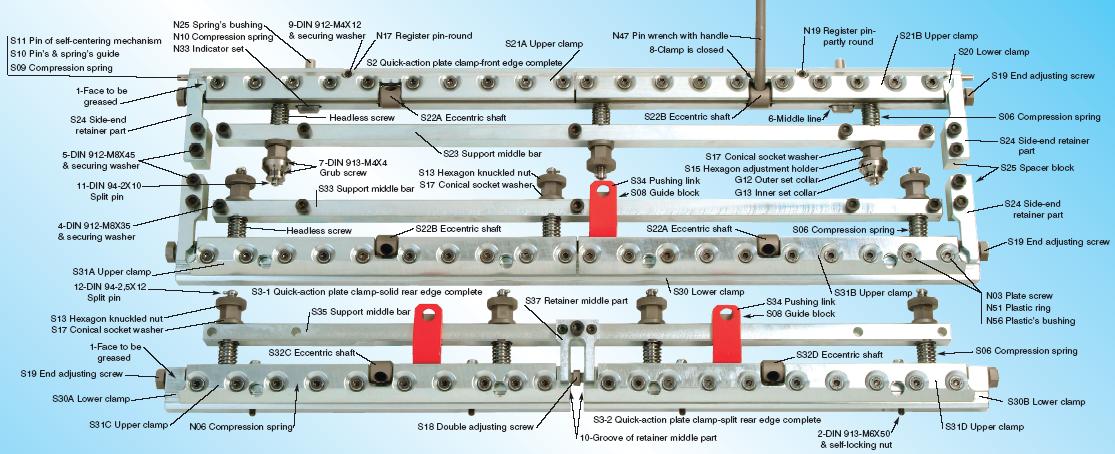
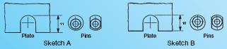
Before you place the new speed clamps onto the machine, please check that the two register pins N17 & N19 are at their correct sides. If they are placed incorrectly, they will need to be changed to the correct sides by loosening the small screws (fig.9) that hold them. The difference between the two sides of pins is shown below in sketches A & B. If you use plates with no holes then you remove the two register pins. If in future you use plates with holes, you reinstall them very easily and simply.
Before you start the placement of the new speed clamps, clean the groove of the cylinder well. Place a fine coat of grease at the bottom of each clamp and on the two sides (fig.1) where the side-end retainer parts hold the clamp in the cylinder. Start by placing the rear clamp in its position inside the cylinder. Place and screw well the provided screws that hold the support middle bar S33 if the rear clamp is solid or the S35 if the rear clamp is split. Place the two side-end retainer parts S24 with their spacer blocks S25 in their positions and screw their screws. Then place the front clamp in its position in the same way and place the other two same sideend retainer parts and their spacer blocks as you did in the rear clamp.
The upper and lower parts of the clamps are connected together with a series of Hexagon socket countersunk head screws N03-M8X25 that are for adjusting, when required, the pressure that holds the plate. The adjustment is always regulated with the plate tightened. For the above adjustment, you must use a long hexagon socket key 5mm by moving it only a little. You have to use some strength because the above screws are secured with a plastic ring N51/N56. There are compression springs N06 between the two parts of the clamp that help to open the upper part (of the clamp). The upper clamp opens and closes with the pin wrench with handle N47. In order to close the clamp, you have to move it forward to the lid end (fig.8). For the opening of the clamp, the pin wrench has to be moved backwards until you feel that it has fallen into a flat gap.
-In order to place the new plate, you have to do the following:
Front clamp: The end adjusting screws S19 must not push the clamp right or left so that the self-centering mechanism S11 can keep the clamp automatically in the center. If during the set-up you use the end adjusting screws to move the clamp right or left, keep these screws tightened till the end of the particular work. Using the operating nuts of the headless screws, adjust the clamp forwards or backwards in position “O”. At this position, the middle thick line (fig.6) of the indicator N33 is aligned with the face of the clamp. Then with a hexagon socket screw key 2mm regulate with the two x two hexagon socket set screws (fig.7) the two precise indicators G13 & G12 to show the number “O”. In the same way adjust the position “O” during the set-up if necessary.
Rear clamp: Unscrew the operating nuts S13 of the headless screws so as to leave enough space for the plate to be installed. If the rear clamp is split, there are four hexagon socket set screws (fig.2) to hold the clamp aligned with the face of the cylinder, without having to unscrew totally the operating nuts of the headless operating screws. You can regulate these screws differently if you think it is necessary. Then bring the clamp in the center using the end adjusting screws S19. If the clamp is split, align the two parts of the lower clamp with the groove (fig.10) of the retainer middle part S37 and correct the margin between them by using the double adjusting screw S18.
-Place the new plate in the clamps.
-Use the pin wrench to close both clamps. With the same pin wrench, move the rear clamp quickly with the pushing link S34 for the solid rear clamp or with the two pushing links for the split rear clamp in order to stretch the plate. Screw the operating nuts of the rear clamps screws by hand at first and then use the wrench for the final tightening of all the nuts of the operating screws of both clamps. -Basically, the operation of the new speed clamps is the same as the old one. The difference is that these clamps hold the plate securely and permanently, offer a faster change of the plates and are for a long-life use.