Spare parts for ROLAND FAVORIT
| Code | Descr | pcs |
|---|---|---|
| FR2 | Whole set | 1 |
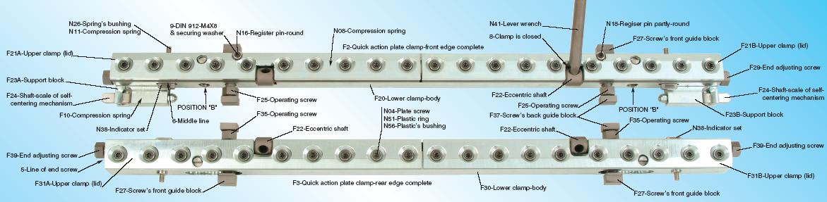
| F2 | Quick-action plate clamp-front edge complete | 1 |
| F3 | Quick-action plate clamp-rear edge complete | 1 |
| F10 | Compression spring of self-centering system | 2 |
| F20 | Lower part-body of front clamp | 1 |
| F21A | Left part of upper front clamp (lid) | 1 |
| F21B | Right part of upper front clamp (lid) | 1 |
| F22 | Eccentric shaft of both clamps | 4 |
| F23 | Support block of self-centering mechanism | 2 |
| F24 | Shaft-scale of self-centering mechanism | 2 |
| F25/F35 | Operating screw of both clamps | 4 |
| F27 | Screws front guide block | 4 |
| F29 | End adjusting screw of front clamp | 2 |
| F30 | Lower part-body of rear clamp | 1 |
| F31A | Left part of upper rear clamp (lid) | 1 |
| F31B | Right part of upper rear clamp (lid) | 1 |
| F37 | Screws back guide block | 4 |
| F39 | End adjusting screw of rear clamp | 2 |
| N04 | Hexagon socket countersunk head screw M8X30 | 40 |
| N08 | Compression spring of clamps lid | 16 |
| N11 | Compression spring of indicator set | 4 |
| N16 | Register pin-round | 1 |
| N18 | Register pin-partly round | 1 |
| N26 | Springs bushing of indicator set | 4 |
| N38 | Indicator set | 4 |
| N41 | Lever wrench Ί10Γ17mm | 1 |
| N51 | Securing plastic ring | 40 |
| N56 | Bushing of securing plastic ring | 40 |
Figures
| # | Descr | pcs |
|---|---|---|
| 5 | Line of end adjusting screw of rear clamp | 2 pos |
| 6 | Middle line of indicator set | 4 pos |
| 8 | Place of lever wrench when the clamp is closed | 4 pos |
| 9 | Hexagon socket head cap screw DIN 912-M4X8 & securing washer | 2 pcs |
The placement of Speed Clamps for ROLAND FAVORIT
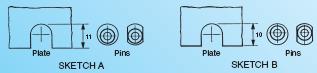
Remove the old clamps by unscrewing the screws that hold the two operating screws back support parts. Pay attention to the inside grooves of both sides of the cylinder cavity. There is a small round piece of hard steel in each groove that sometimes it is broken in small pieces that have to be removed. Clean the whole cylinder cavity well and particularly the grooves of the cylinders sides and the grooves of the screws back support parts. Spread a fine film of grease on all the surfaces of the grooves. Check the front clamp if the two register pins N16 & N18 are at their correct sides. If they are placed incorrectly, they will need to be changed to the correct sides by loosening the small screws (fig.9) that hold them. The difference between the two sides of pins is shown above in sketches A & B. If you use plates with no holes then you remove the two register pins. If in future you use plates with holes, you reinstall them very easily and simply.
You must also check if the two operating screws of each clamp are at the correct distance. If they are not, you have to unscrew the operating screws and put them in the other position “B”. Place the clamps in their positions, in the cylinder cavity, with the screws front and back guide blocks. Special care is required when tightening the screws that hold the screws back support parts. The operating screws must rotate smoothly and the clamp mustnt move forwards-backwards.
THE OPERATION OF SPEED CLAMPS
The upper and lower parts of the clamps are connected together with a series of hexagon socket countersunk head screws N04-M8X30 that are for adjusting, when required, the pressure that holds the plate. The adjustment is always regulated with the plate tightened. For the above adjustment, you must use a long hexagon socket key 5mm by moving it only a little. You have to use some strength because the above screws are secured with a plastic ring N51/N56. There are compression springs N08 between the two parts of the clamp that help to open the upper part (lid). The upper clamp opens and closes with the lever wrench N41. In order to close the clamp, you have to move it forward to the lid end (fig.8). For the opening of the clamp, the lever wrench has to be moved backwards until you feel that it has fallen into a flat gap.
-In order to place the new plate, you have to do the following:
Front clamp: The end adjusting screws F29 must not push the clamp right or left so that the self-centering mechanism F24 can keep the clamp automatically in the center. If during the set-up you use the end adjusting screws to move the clamp right or left, keep these screws tightened till the end of the particular work. Using the operating screws F25, adjust the clamp forwards or backwards in position “O”. In this position, the middle thick line (fig.6) of the indicator N38 is aligned with the face of the clamp.
Rear clamp: Unscrew the operating screws F35 so as to leave enough space for the plate to be installed. Then bring the clamp in the center using the end adjusting screws F39 that have a line on them (fig.5) to show that the clamp is in the center.
Place the new plate as always.
Remember to press the lever wrench N41 so that the clamp is closed and the lever wrench touches the upper part of the clamp (fig.8). It is better not to close the first part of the clamp to the end. It is preferable to close the second immediately and then go back to the first for the final closure. In this way the plate does not warp. After that, screw the operating screws F35 of the rear clamp completely and then do the same at the operating screws F25 of the front clamp. Basically, the operation of the new speed clamps is the same as the old one. The difference is that these clamps hold the plate securely and permanently, offer a faster change of the plates and are for a long-life use.